SERVICE INFORMATION
GENERAL
• During PDI always ensure that there are no malfunction codes stored in the ECUs memory.
• Ensure ECUs and harness connectors are fastened securely. A poor or loose connection can cause high voltage surge and result in damaging the integrated circuits in ECUs.
• Bending or twisting the control cable will impair smooth operation and could cause the cable to stick or bend, resulting in loss of control on the vehicle.
• If the Malfunction Indicator Lamp (MIL) glows, follow the Malfunction Diagnosis procedures to remedy the problem.
• In case of any DTC occur in the VCI, always follow the steps in the troubleshooting.
• A faulty electrical system is often related to poorly connected or corroded connectors. Check those connections before proceeding.
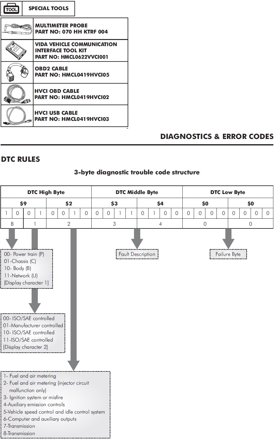
• Use a Vida vehicle communication interface tool kit (Vida VCI) (part no. HMCL0622VVCI001 for troubleshooting inspection.
• While installing the new ECUs always follow the pairing process.
• For troubleshooting, remove the body panels.
MALFUNCTION DIAGNOSTIC
PROCEDURE
If malfunction indicator lamp (MIL) glows on TFT it indicates,
there is an abnormality in the vehicle.
If you wish to read the DTC code, perform the following:
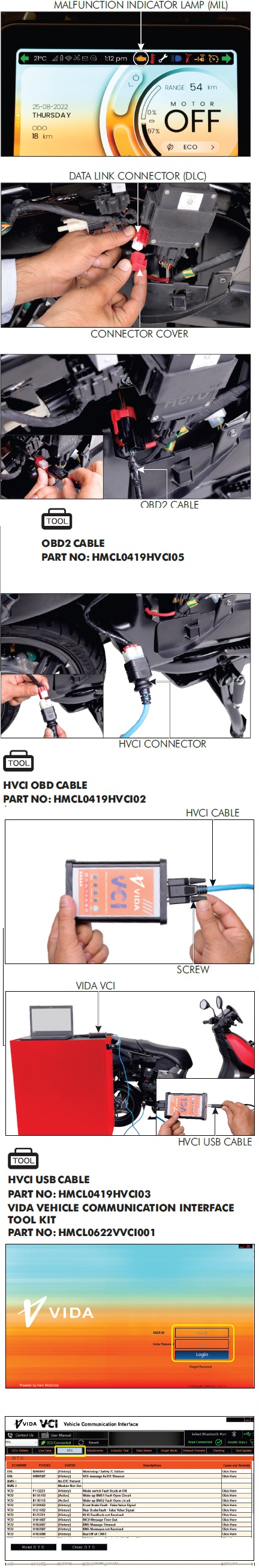
MALFUNCTION CODE READING
PROCEDURE
Turn the vehicle power “OFF".
Remove the right body cover.
Disconnect the connector cover from the data link connector (DLC).
Connect the HVCI OBD2 cable to the data link connector (DLC).
Connect the HVCI OBD cable to OBD2 cable.
Connect the HVCI connector to the Vida VCI and tighten it by rotating its screw.
Connect Vida VCI and Laptop/Desktop either with HVCI USB cable or using the Bluetooth connectivity.
HVCI USB CABLE
PART NO: HMCL0419HVCI03
VIDA VEHICLE COMMUNICATION INTERFACE
TOOL KIT
PART NO: HMCL0622VVCI001
Turn the vehicle power “ON".
NOTE: -
Motor should not be “ON” during the process.
Open Vida VCI application and login with username and password credentials.
Click on to “DTC” tab to view the diagnostics trouble codes stored in the ECUs memory.
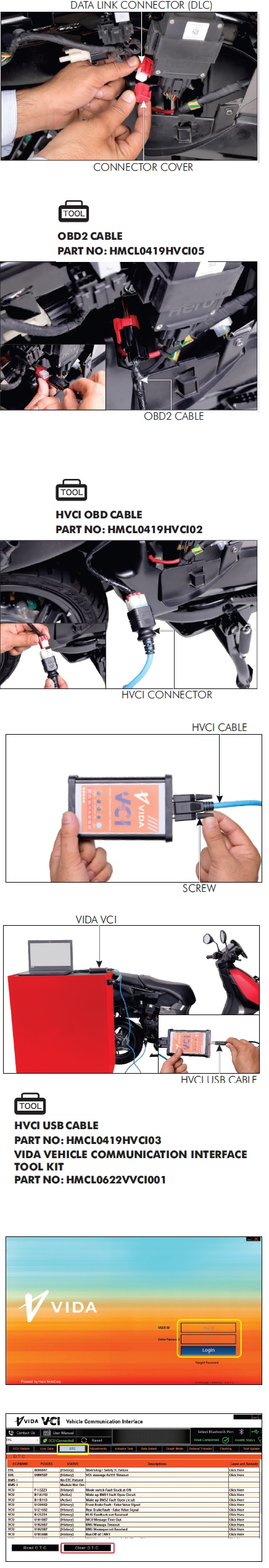
MALFUNCTION CODE ERASING
PROCEDURE
Turn the vehicle power “OFF".
Remove the right body cover.
Disconnect the connector cover from the data link connector (DLC).
Connect the HVCI OBD2 cable to the data link connector. (DLC).
OBD2 CABLE
PART NO: HMCL0419HVCI05
Connect the HVCI OBD cable to OBD2 cable.
HVCI OBD CABLE
PART NO: HMCL0419HVCI02
Connect the HVCI connector to the Vida VCI and tighten it by rotating its screw.
Connect Vida VCI and Laptop/Desktop either with HVCI USB cable or using the Bluetooth connectivity.
HVCI USB CABLE
PART NO: HMCL0419HVCI03
VIDA VEHICLE COMMUNICATION INTERFACE
TOOL KIT
PART NO: HMCL0622VVCI001
Turn the vehicle power “ON".
NOTE: -
Motor should not be “ON” during the process.
Open Vida VCI application and login with username and password credentials.
To clear the DTC codes, go to DTC tab and click on “Clear DTC” button to clear the existing error codes.
VCI TOOL NOT RESPONDING
Check the connection between laptop/computer and VCItool.
Check the connection between VCI tool and OBD connector.
Turn the vehicle power “ON" and check if the VCI is responding.
If VCI is not responding, Turn the vehicle power “OFF" and check the loose or poor connection at VCU 64P connector and OBD connector.
Turn the vehicle power “OFF" and disconnect the VCI tool from OBD connector.
Check the VCI cable connection on OBD connector.
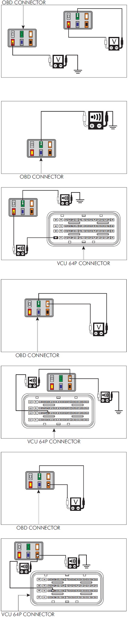
1. Turn the vehicle power “ON" and measure the voltage on the OBD connector.
CONNECTION
Red/Yellow- Green
STANDARD: Battery Voltage
If voltage exist, then go to step number 2.
If voltage does not exist, measure the voltage between the
red/yellow and ground.
CONNECTION
Red/Yellow- Ground
STANDARD: Battery Voltage
If voltage exist between red/yellow and ground:
Check the continuity of green wire of OBD connector and ground.
CONNECTION
Green- Ground
STANDARD: Continuity
If continuity does not exist, then replace the wiring harness and inspect again.
If the voltage does not exist between red/yellow and
ground:
Disconnect the VCU 64P connector and check the continuity between OBD connector and VCU 64P connector.
CONNECTION
Red/Yellow (VCU Pin- Q1)-Red/Yellow
STANDARD: Continuity
Green- Ground
STANDARD: Continuity
If continuity does not exist, then replace the wiring harness and inspect again.
2. Check the OBD harness CAN-H voltage at OBD connector.
CONNECTION
Orange/White-Green
STANDARD: 2.34 V
If voltage does not exist, disconnect the VCU 64P connector and check the continuity between the OBD connector and VCU 64P connector.
CONNECTION
Orange/White (VCU Pin-M2)-Orange/White
STANDARD - Continuity
Orange/White-Ground
STANDARD: No Continuity
If any abnormality is found, replace the wiring harness and inspect again.
3. Check the OBD harness CAN-L voltage at OBD connector.
CONNECTION
Orange/Black- Green
STANDARD: 2.35V
If voltage does not exist, disconnect the VCU 64P connector and check the continuity between the OBD connector and VCU 64P connector.
CONNECTION
Orange/Black (VCU Pin-N2)-Orange/Black
STANDARD: Continuity
Orange/Black-Ground
STANDARD: No Continuity
If continuity does not exist, replace the wiring harness and inspect again.
If all above connections are normal then check with a known good Vida VCI tool and inspect again.
DIAGNOSTIC TROUBLE CODE CHART
To identify the vehicle malfunction, connect the Vida VCI & check the malfunction as per the malfunction code and repair or replace the defective component. After replacing a defective component, again check for any malfunction.
